The First Time I Trusted CADD
The First Time I Trusted CADD
ARLINGTON, MASSACHUSETTS 2007
This statement is probably one of the most unusual things you might hear from an architect today, given the profession’s dependence on technology, but I say this in the context of my own building projects, not my professional work. As a kid, I built with wooden blocks, with nary a computer or drawing in sight. At age 16, I began to work construction. My plan was to be a carpenter’s helper one summer, a plumber’s helper another, and finally an electrician’s helper in order to learn all the trades. As I started in carpentry and fell in love with it, I never pursued the other trades. At 17, I began working with two high school shop teachers, one who knew electrical work and one who knew plumbing work, and we started a design-build company doing residential work. As I was always on site doing the building as well, I could wait until the last possible moment to make a decision and refine the design with much more knowledge of what I was dealing with. These were most often renovation projects so there were always existing conditions and constraints. I was fortunately born with the ability to see and think in three dimensions and this made it all easier.
As we contemplated the renovation of the kitchen in our 1895 Colonial revival shingle style house, which existed with small service spaces blocking access to the back yard, it became apparent that we needed to flip the plan. The goal was to move the side door to the middle of the house so the kitchen could slide back and open to the yard. After a lot of sketching, my wife solved the floor plan, but the elevation remained a challenge due to the existing balanced composition on the side elevation. This composition was not symmetrical, but balanced about the centerline that held the ornamental stair window, a small roofed window in the basement stair, and the attic window.
A trip to Jekyll Island, Georgia and the Jekyll Island Club opened my eyes to a solution that would help solve the puzzle and allow us to proceed with the development of the design. The Jekyll Island Club was founded in 1886 as a winter hunting club for society’s elite, including the Astors, the Rockefellers, the Goulds, and the Morgans. The 1929 Morgan indoor tennis pavilion at the club provided the inspiration for a projected bay roof (see title photo) that would allow us to have asymmetry below, move the entry to the middle of the elevation, and still visually balance the bay window already on the house. After seeing this example and being enamored with the way the wall flowed into the roof, we began to notice other examples, some done well and others gone a bit astray, having lost their elegance in unfortunate subsequent material choices.
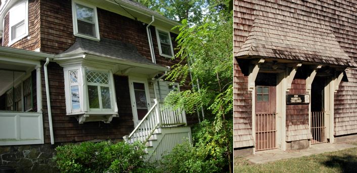
Left: Asphalt shingles replacing the original wood shingles diminishes the effect
Right: Jekyll Island Tennis Pavilion entry
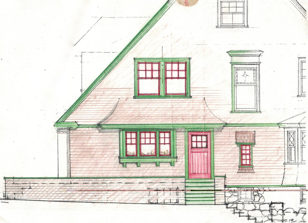
This elevation sketch proved that the concept worked and we proceeded to make plans to replace the unsympathetic 1950s steel frame sash. The builder in me wanted to tackle this project so I decided to construct it myself. I began to think through the logistics of how to make things work and still relate visually to the bay on the other side of the elevation.
Knowing that I could freehand the curved pattern of the typical rafters, I looked at how far I could extend the roof to adequately shelter the door. In all my previous personal projects, I was able to construct the projects largely without full scale drawings. Many times before when building a roof, I had framed both sides of a hip and then figured out the hip rafter in place. Here the hip rafter was a compound curve with a bevel on top that changed through the arc of the curve. Not only that, the shingles needed to transition into the wall at the 5-inch exposure that was typical of the wall and be vertical by the time they hit just below the window sill. I had the feeling that my typical strategy for figuring out the hip rafter would be difficult in this situation, so I started considering alternatives.
Around this time, the 3-D modeling program SketchUp was gaining traction in the office and I asked a young designer, Buck Sleeper (yes, that’s his real name) if he could model the roof and he said he could. He first modeled the rafters based on a sketch I gave him and then ultimately the hip rafter. We printed both patterns out full scale on the plotter. I took them home and proceeded to cut all the rafters using the patterns. It was a leap of faith to cut those two hip rafters and hope that they were right. I did not realize at the time that I was making the same mistake contractor’s often do by taking an element of the drawing (the patterns) out of its context (the model). After installing all the right angle rafters, I brought the hip rafters up and put them in to the corner of the perpendicular rafters and they were too short! First I was frustrated and pissed, and then began to figure out what was wrong. “When in doubt, look at the drawings,” I said to myself. I went back in the house and onto the computer to look at the SketchUp model. I noticed that he had put the hip not in the corner as was typical, but springing from the point of the sidewall rafter which had to be chamfered for the front slope of the roof (see drawings below).
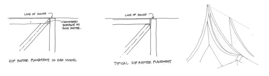
Left: What was modeled in the computer
Center: What I assumed was modeled, based on my experience
Right: Perspective showing modeled hip rafter
I climbed back on the ladder, placed the hip rafters per the model, and they both fit perfectly. The computer modeling, full-size pattern-making and rafter installation worked after all. The roof took on a very nice shape, like the skeleton of a boat hull upside down. The photo below shows the rope holding up the soffit framing which I pre-fabricated on the ground, set on blocks, used a pulley system to bring it level, and then tied it off to the tree before fastening to the house. When working alone, sometimes you have to get creative. I then laid out the rafters and followed it with two layers of ¼” plywood conforming to the curve. This was topped with ice and water shield and a spun polyester matrix that allows the shingles to dry on both sides.
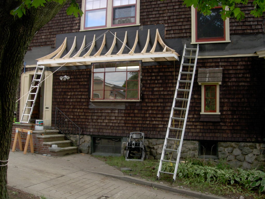
Two Layers of ¼” plywood conform to the curve 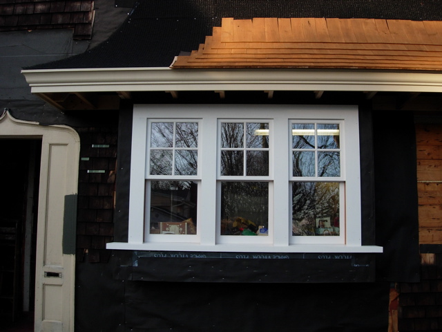
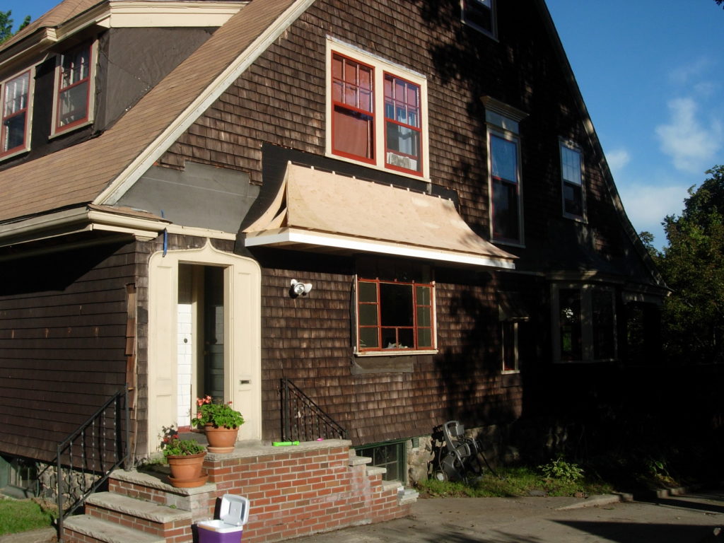
Beginning of shingle coursing
I had recently finished a custom house on the coast of Maine and the builder offered to come down and help me install the doors and windows and shingle the roof. The picture above is how far they got in one day with the shingling. When I got home that night I wanted to yell at them for not getting very much done in a whole day with two guys. Fortunately, I decided not to yell and it was a good thing, because when I picked it up to finish it, I found out that weaving a corner on a compound curve is a very slow process. It also makes you understand how someone could choose to replace the wood with asphalt shingles which bend and cut much easier with such complex geometry.

I had originally expected that the shingle courses would line up going from the wall to the roof, but it was quickly pointed out to me by the contractor that this was impossible due to the different geometries. What was I thinking? So we worked it out that the shingles gradually adjust as they transition up the roof to the more vertical portion, where they align with the course running across the top of the roof and below the window.
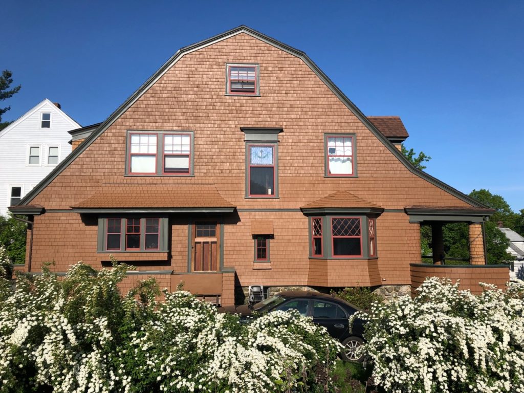
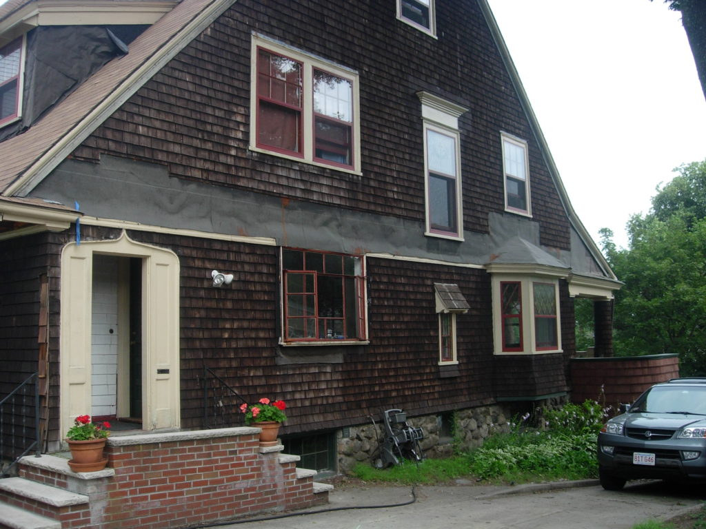
The finished photograph shows how the two bays balance the composition and how moving the side entrance to the middle of the house improved the interior flow and connection to the back yard. While not in a historic district, the house itself is on the local register. Therefore, the local historic commission must approve exterior elevation changes visible from the street. Showing the precedents from Jekyll Island and also some local ones from the town of Arlington led to this solution receiving unanimous approval. People often don’t realize that it was not like this originally.
There are a few takeaways from undertaking a project like this. One, looking for precedents and using them appropriately is a great way to solve sticky design challenges. Roger Clark, one of my college professors wrote a book called Analysis of Precedents that described how analyzing iconic historic buildings taught you the underlying organization strategies of plan and elevations which allowed young architects to gain an understanding of things that give rigor to building design.
Second, building is a way we architects come to understand what we are asking people to do. It is not the first time I have learned that lesson. In my design-build company my partners would give me a very hard time if they were standing there waiting too long for me to figure out how to solve a problem out on the construction site. It was not a great feeling, so I became trained to thoroughly think through what I was asking people to do. When I was in high school, I helped an architect build his own home and I asked to work in his office thereafter. He told me to work construction until I got out of school because I had the rest of my life to work in an office. It was good advice.
Lastly, computer aided design and drawing (CADD) is a great tool that can model things that would be difficult to figure out any other way. It is very accurate, sometimes exceedingly so, and that accuracy cannot always be replicated in the field. When the input is good, as is it was in this case, you can be highly confident in the output. I found out that you could indeed trust CADD.